Problem C2.1. Unsteady Viscous Flow over Tandem Airfoils
Overview
This problem is aimed to test the unsteady interaction of a vortex with a solid wall. Specifically, several cases are defined that address both unsteady pressure generation and viscous separation in a 2D framework by using a pair of airfoils. The geometry remains relatively simple and provides a test bed for several different types of analysis. In general, the time history of the lift coefficient on the aft airfoil will be used as a metric. Other quantities to assess would be the pressure distribution on the two airfoils and the total circulation in the problem obtained by integrating the vorticity throughout the domain.
Governing Equations
The governing equations for this problem are the 2D compressible Navier-Stokes equations with a constant ratio of specific heats equal to 1.4 and a Prandtl number of 0.72. Compressibility is not anticipated to be a significant player in these problems. Specific conditions will be provided with each subcase.
Flow Conditions
Two different problems are defined. In each of these cases, the Mach
number (![]() ) is 0.2, the angle of
attack (a) is
) is 0.2, the angle of
attack (a) is ![]() , and the Reynolds number
based on the chord of one of the airfoils is 1000.
, and the Reynolds number
based on the chord of one of the airfoils is 1000.
・ Case A examines the evolution of the flow field from a prescribed initial solution that is C1. In this condition, d is the distance to the closest wall, which is often required for turbulence models. Density and pressure are initialized to their free stream values.

with ![]()
・ Case B is closer to an impulsive start
condition. Let ![]() with
with ![]() Density and pressure are again set to uniform free stream values.
Density and pressure are again set to uniform free stream values.

with ![]()
Geometry
The basic geometry for this case is two relatively positioned NACA0012 airfoils. As done in problem C.1.3, the airfoil geometry is given by
![]()
The leading airfoil is rotated by d about (0.25, 0) while the trailing airfoil is translated by (1 + dsep,
-doff ).
For the present case, take ![]() , dsep = 0.5, and doff = 0. The far field
boundary can be determined such that the steady state lift coefficient of both
airfoils (based on a reference length of 1 chord) varies less than 0.01 counts.
, dsep = 0.5, and doff = 0. The far field
boundary can be determined such that the steady state lift coefficient of both
airfoils (based on a reference length of 1 chord) varies less than 0.01 counts.
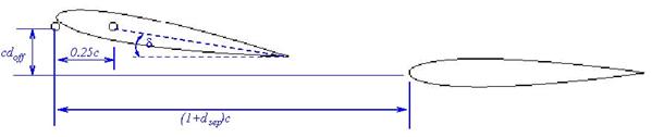
Figure 2.1 Geometry for Tandem Airfoils
Requirements
1. If you generate new meshes, please adhere to the following guideline: The far field should be a circle, centered at the mid chord of the first airfoil with a radius of 1000 chords. Do not apply any vortex correction at the far field.
2. Perform the indicated simulation to an elapsed time of
20 convective lengths (![]() ), maintaining a time
history of the lift and drag coefficients on the aft airfoil. Perform a time
step/mesh resolution study to ensure the lift coefficient is resolved to within
1 count throughout the time interval. Track the work units for this simulation.
(Optional: repeat at different orders of accuracy)
), maintaining a time
history of the lift and drag coefficients on the aft airfoil. Perform a time
step/mesh resolution study to ensure the lift coefficient is resolved to within
1 count throughout the time interval. Track the work units for this simulation.
(Optional: repeat at different orders of accuracy)
3. Provide work units, the converged time history of lift
and drag on the aft wing, nDOFs in the solution, and the distance to the far field
boundary for each case. Submit this data to the workshop contact. Use ![]() to non-dimensionalize time.
to non-dimensionalize time.